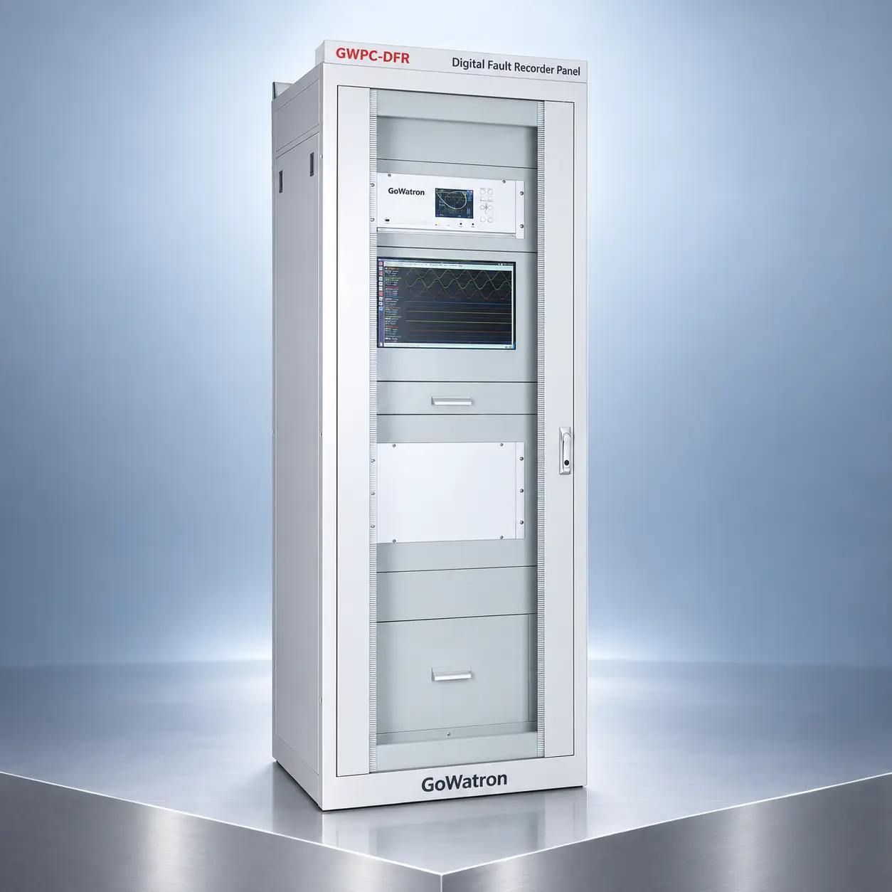
GWPC-DFR Digital Fault Recorder Panel
Product Desc
- The GWPC-DFR continuously acquires analogue quantities and binary status signals from primary equipment, instrument transformers, protection and control devices, and station service power systems.
- Typical input signals include:



Fault Recording
Transient & Continuous Recording

SOE Recording
Time-Stamped Event Records

Fault Analysis
Fault Location & Event Analysis

Precise Time Sync
IRIG-B · SNTP/NTP · PTP

Protocols
IEC 61850 · IEC 104/103 · Modbus

COMTRADE
Standard Record Export

Warranty
2 Year Warranty
Protection Functions
Phase Overcurrent Protection
- (ANSI 50) Instantaneous Overcurrent Stage I
- (ANSI 51P) Definite-Time Overcurrent Stage II
- (ANSI 51) Definite-Time Overcurrent Stage III
- (ANSI 51) Inverse-Time Overcurrent
- (ANSI 50/51) Close-On-Fault Acceleration Protection
- (ANSI 51) Overload Protection
Asynchronous Motor-Specific Protection
- (ANSI 48) Motor Start Blocking
- Earth Zero-Sequence Protection
- (ANSI 51N) Definite-Time Zero-Sequence Overcurrent
- (ANSI 51N) Inverse-Time Zero-Sequence Overcurrent
Autoreclosing
- (ANSI 79) Line Autoreclosing
Voltage/Frequency Abnormal Condition Protection
- (ANSI 59) Overvoltage
- (ANSI 27) Undervoltage
- (ANSI 59N) Zero-Sequence Overvoltage
- (ANSI 81L) Underfrequency Load Shedding
- (ANSI 60) VT Disconnection Alarm
- Shunt Capacitor Bank Dedicated Protection
- (ANSI 60) Capacitor Unbalance Overvoltage
- (ANSI 46) Capacitor Unbalance Overcurrent
- (ANSI 50) Capacitor Switching Inrush Protection
Unbalanced Fault Protection
- (ANSI 46) Negative-Sequence Overcurrent
Secondary Circuit Supervision
- (ANSI 74) Circuit Breaker Control Circuit Supervision
- (ANSI 27/59) System Loss-of-Voltage Protection
Non-Electrical Quantity Protection
- (ANSI 63) Transformer Cabinet Door Interlock
- (ANSI 63) Buchholz Trip Protection (Heavy Gas)
- (ANSI 63) Buchholz Alarm (Light Gas)
- (ANSI 63) Winding Overtemperature Trip
- (ANSI 63) Equipment Overheating Warning
- (ANSI 95) Remote Load Shedding Trip
Other Functions of the Product

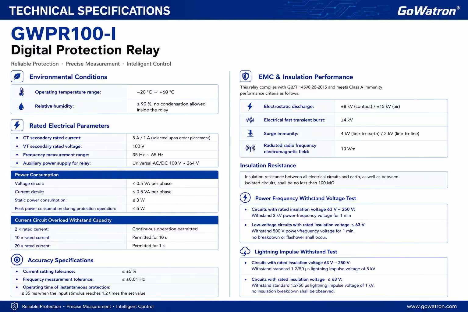
Technical Specifications
Structure and Mounting Dimensions
- Mounting Type: Standard flush panel mounting. It can be installed singly on local or assembled in multiple units inside centralized control racks.
- Rear Board Dual-Module Plug Design:
- Plug A: Analog quantity acquisition circuit, RS485 communication circuit
- Plug C: Relay auxiliary power supply, 10-channel digital inputs, 4 groups of relay output contacts
- Grounding Requirement: The rear grounding terminal must be reliably connected to ground via copper conductors with a cross-sectional area of no less than 4 mm².

Typical Application Scenarios
- Medium and low voltage distribution systems up to 13.8 kV / 11 kV: for feeders, distribution transformers, shunt capacitor banks and bus tie breakers
- Medium and low voltage asynchronous motor loops: Integrated protection relay for 0.4 kV / 6 kV / 11 kV / 13.8 kV motors, covering start-up, overload, unbalance and overtemperature fault protection
- Distributed photovoltaic grid connection points: Backup protection relay for 13.8 kV / 11 kV / 400 V PV grid-tied sides, monitoring overcurrent, over/undervoltage and earth faults
- Industrial plant power distribution rooms: Local protection relay for switchgears in chemical, manufacturing, data center and industrial park projects
- Small substations, outdoor prefabricated substations and switching stations: Specialized integrated protection relay for outdoor environments with wide temperature range and high electromagnetic interference